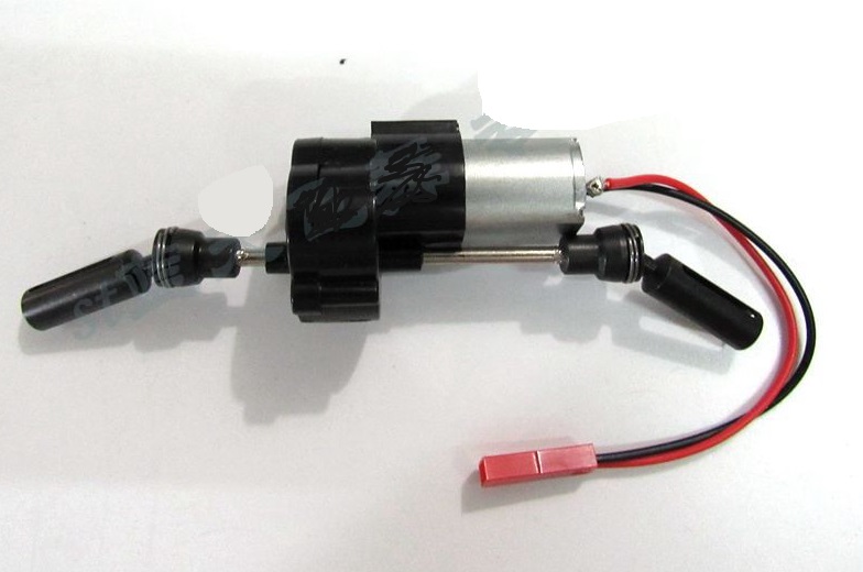
WPL B16 Parts-30 Upgrade Metal gear,Upgrade Metal steering cup and Upgrade Metal drive shaft,WPL B16 B-16 RC Car Parts,WPL 6X6 Parts,WPL B16 B-16 RC Military Truck Spare parts Accessories,WPL 1:16 Off-road Truck Parts
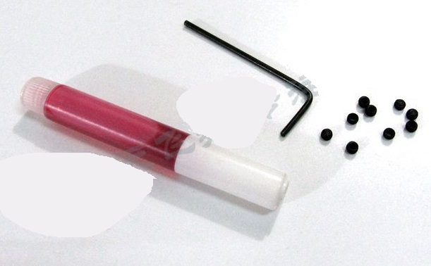
1 First we have to prepare the machine screw, the machine meter screwdriver, and the screw glue. . The machine screw should be glued with a little screw glue and then installed on the screw hole, otherwise it will loosen. . . After tightening the screws, do not twist the screws too much, otherwise the Screws may slip, slippery.
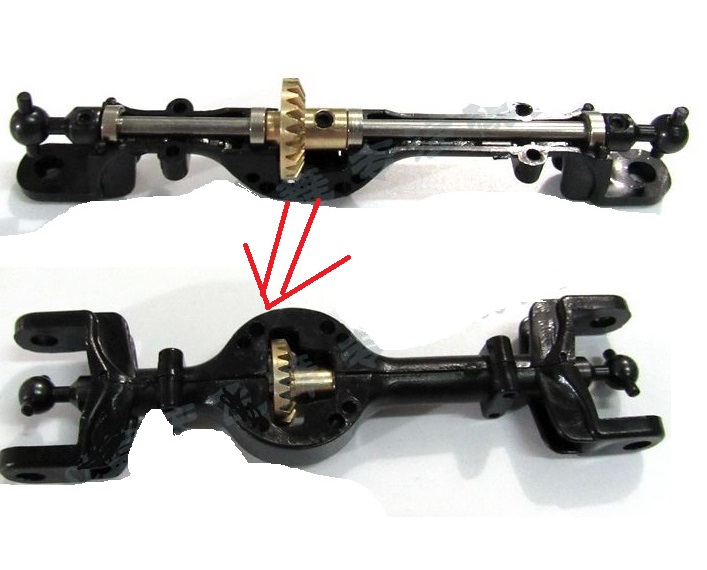
A) Front axle installation diagram
2 First install the front axle, we take out the short shaft, 1 pair of ball heads, 1 big gear and 4 small bearings。 The machine screw should be glued with a little screw glue, then install, Pay attention: when you install the ball head onto the Front shaft, do not put it too tight inside, otherwise the outer casing of the bridge will not be installed. The picture after installation is as shown below.
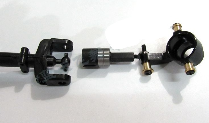
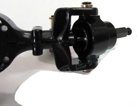
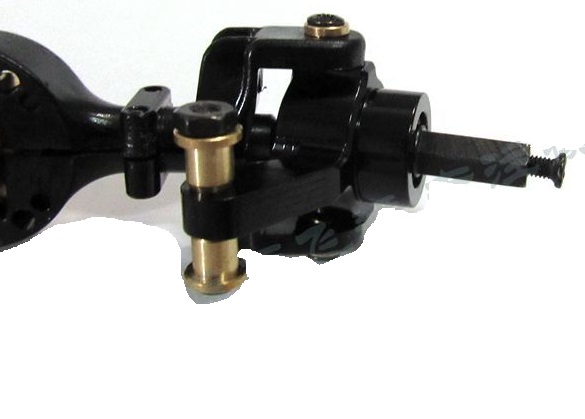
4 Next, install the cups and steering cups on both sides of the front axle.
The upper and lower copper sleeves of the steering cup are mounted on the bridge (as shown below) Note: Screws should be glued a little glue to prevent the screws from falling out.
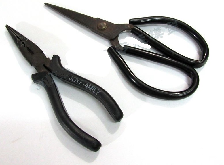
7 This is our general tool for dismantling plastic drive shafts, pay attention to safety.
8 The next step is to remove the plastic drive shaft.
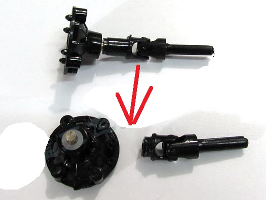
9-10 Before you istall the Output shaft cover ,you must install 2pcs bearing on the Output shaft cover ,then install the small gear .
You needs to forced, destroyed and dismantled this parts ,then can install it . You can also bake the shaft part with a lighter, then pull it out, Usually roasting 6 second then can pull it out.
We usually use scissors and needle-nosed pliers. After the disassembly, Keep the metal shaft and Input cover .
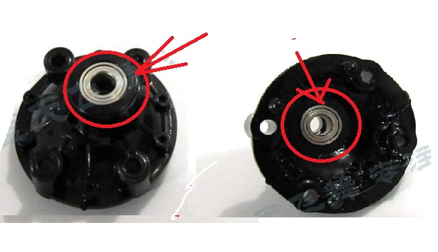
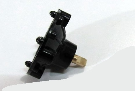
12 After installation, as shown below. . Remember The machine screw should be glued with a little screw glue.
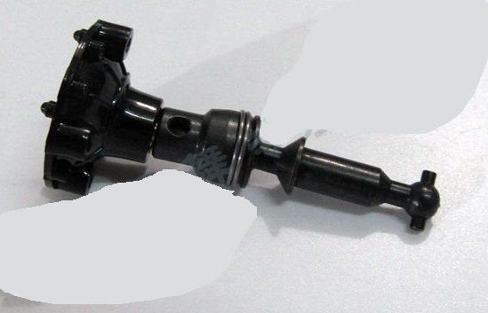
B) The Rear axle installation as shown below:
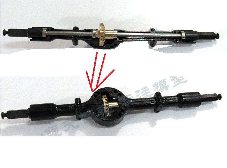
1) When installing the cover on the front and rear axles, apply a little butter to the gears and install 4 long screws. The screw should not be twisted too tightly, otherwise the gears are too tight and easy to get stuck.
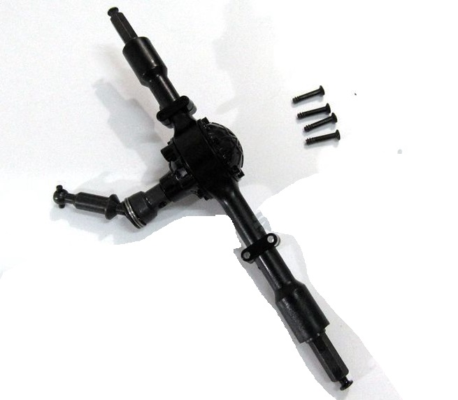
2) screws remember to apply a little screw glue
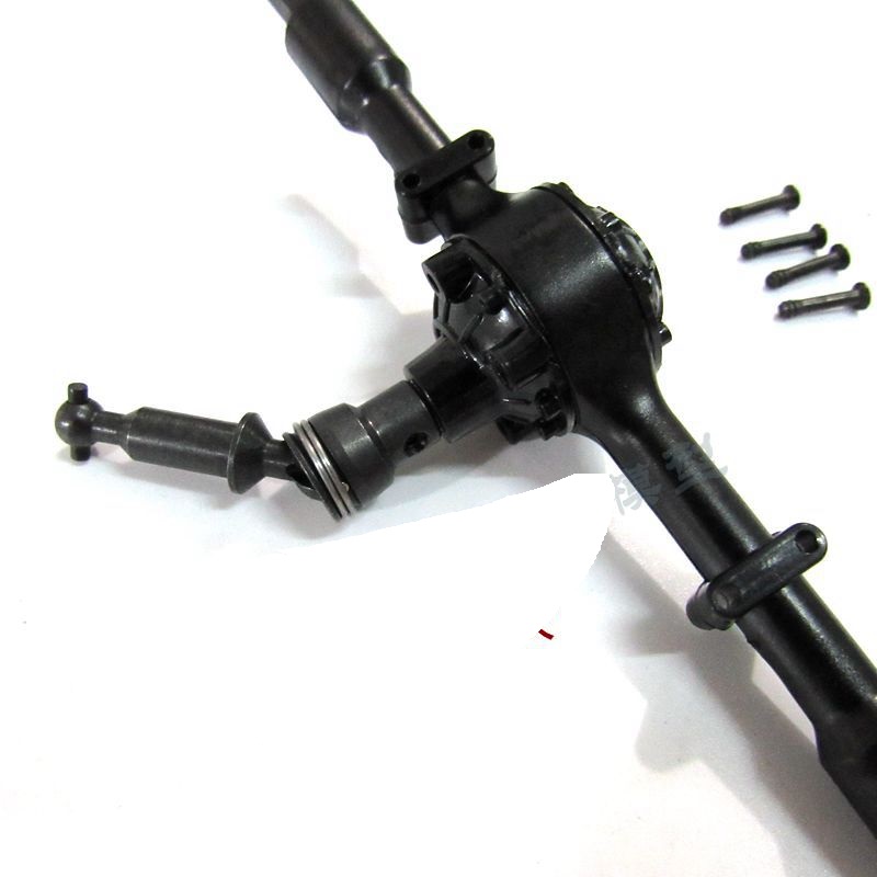
C)Installation the drive gear box diagram
1 Disassemble the plastic drive shaft at both ends of the power transmission box. The Disassemble diagram is as follow , Also we prepare the sickle. tool(We will send you a sickle for free ).
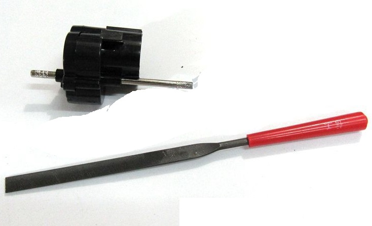
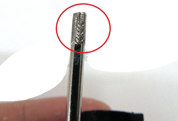
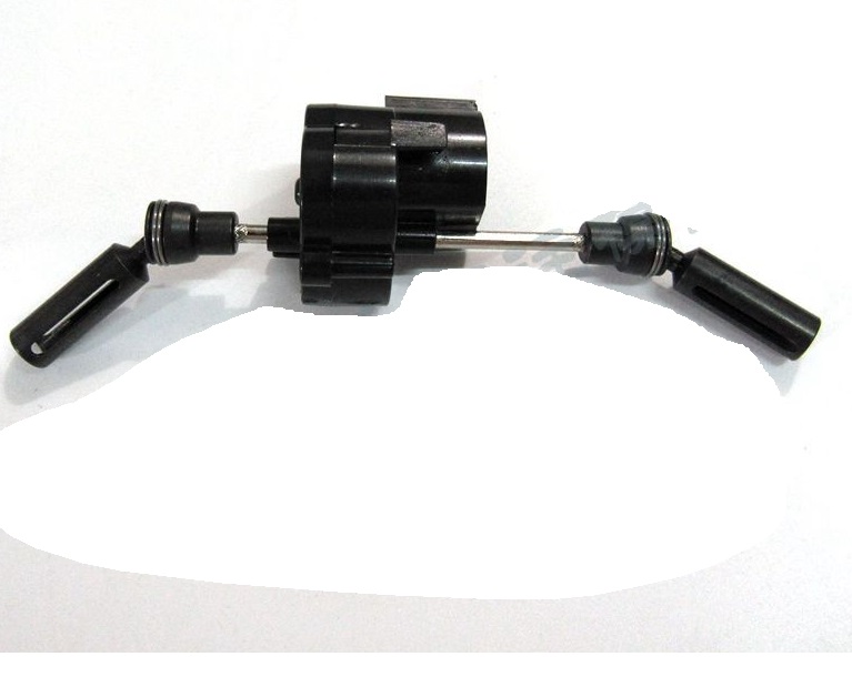
2 Mounting the metal drive shaft. We need to use a sickle to polish a plane surface on the Tail end of the shaft,Then use JIMI Machine screws to fix it . Remember to apply glue to the screws..
3 Install as shown below. The 130 180 motors are both suitable for installation.
4 This figure is a 180 motor installation diagram.